
CCS Fast-Charge Kit
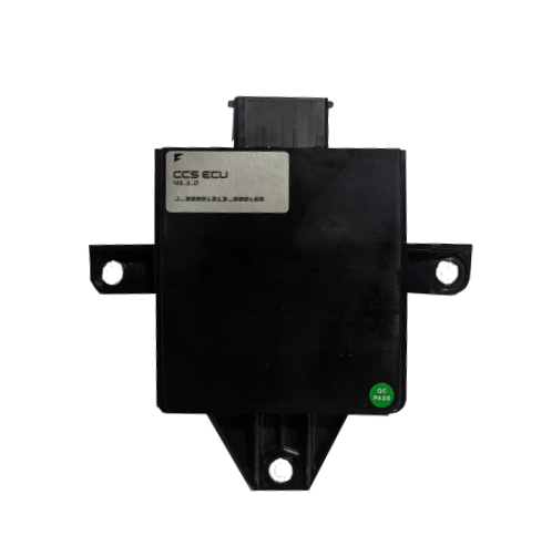
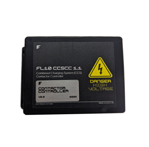
Add AC + DC combined-charging (CCS) fast-charge capability to an EV conversion through a single outlet. A complete system - contactor controller, CCS ECU, charge outlet, locking motor, stop switch, contactors and fuse - built around the Orion BMS 2. Choose your standard below; follow the full user guide for every safety-critical step.
Indicative shop price, ex-VAT. Quoted per project (shipping, options).
Kit contents
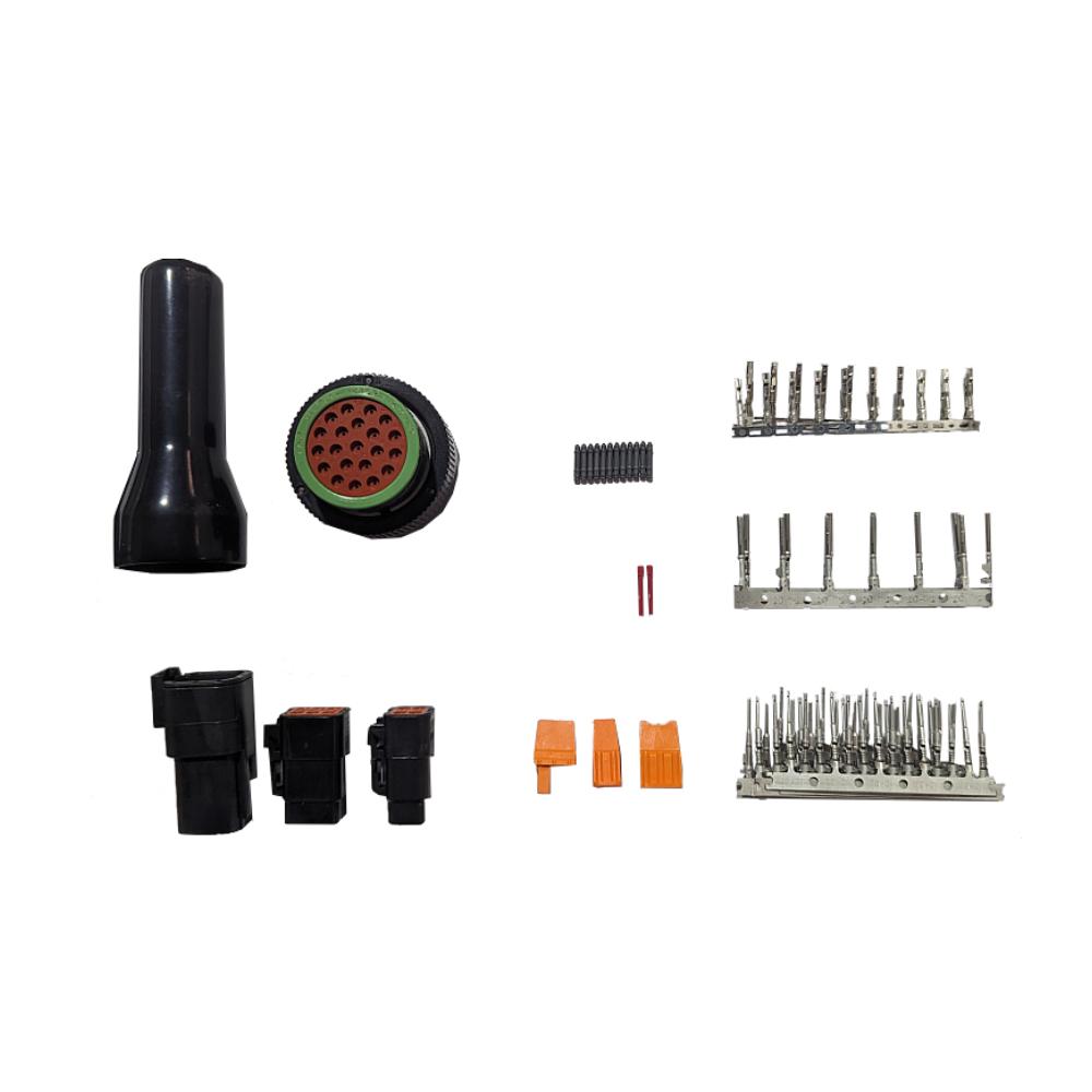
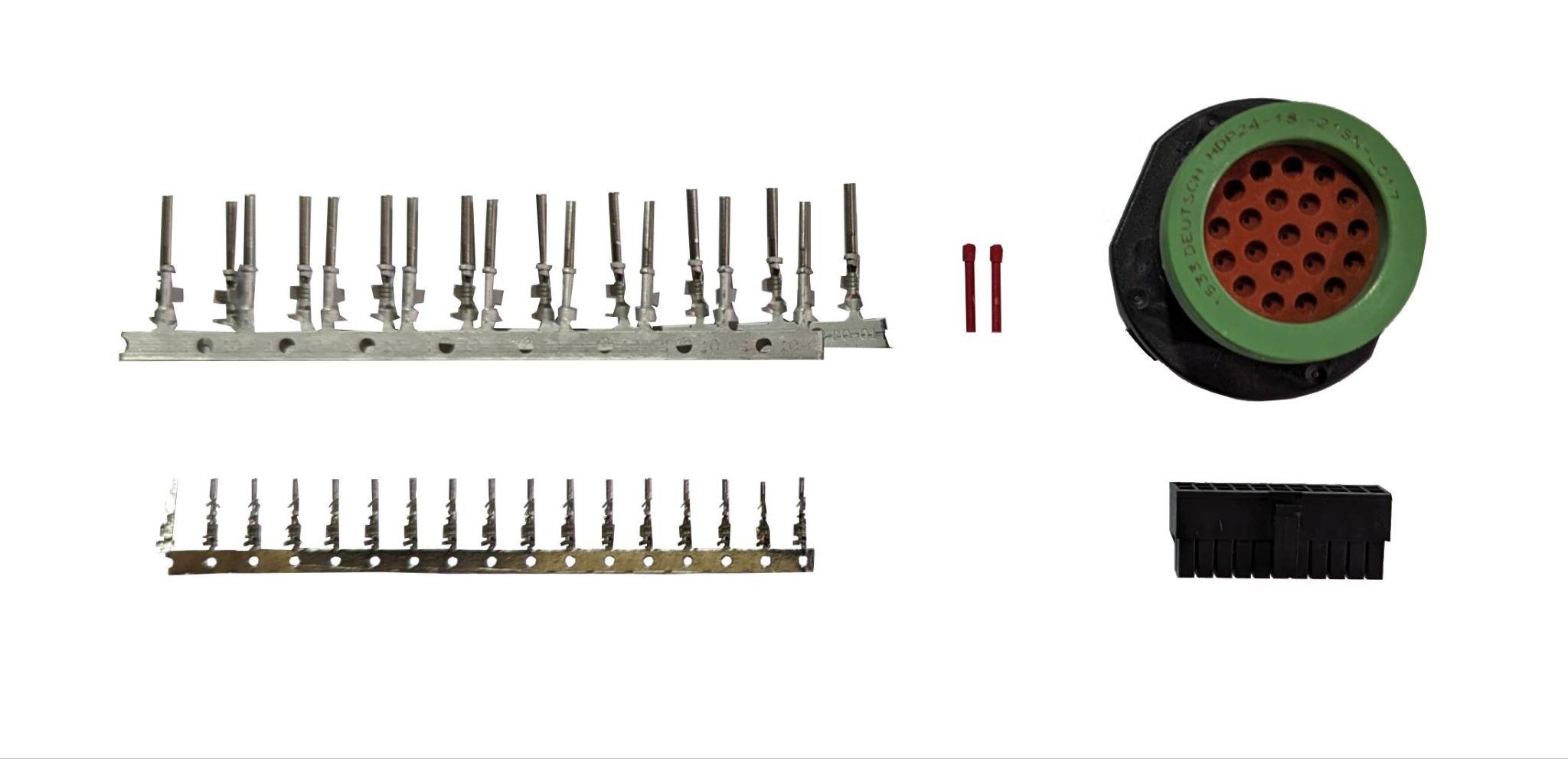
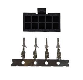
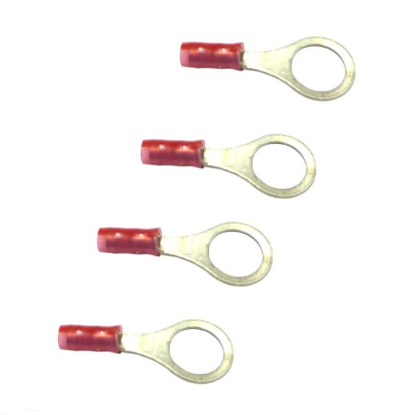
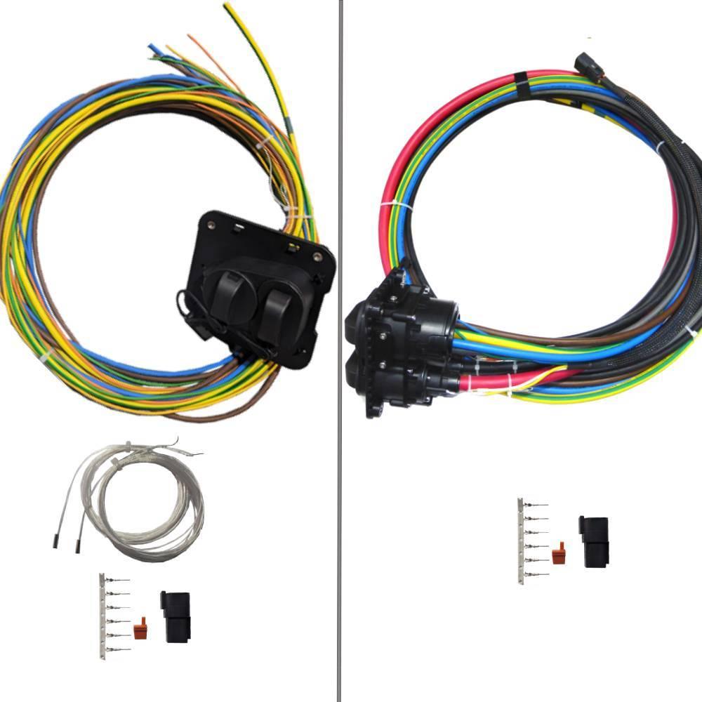
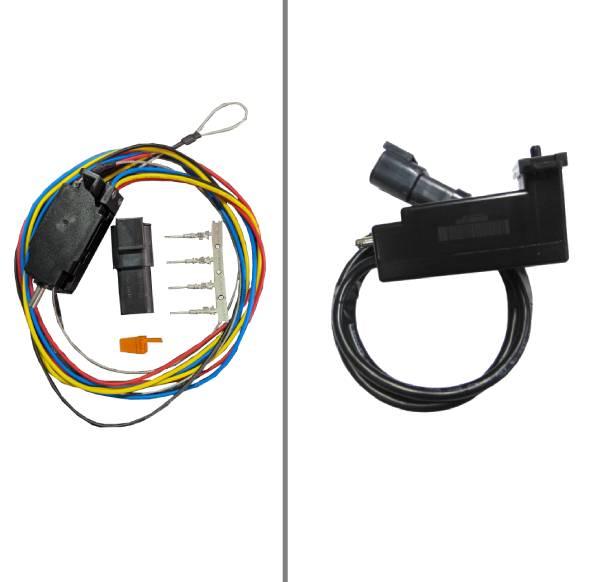
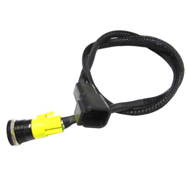
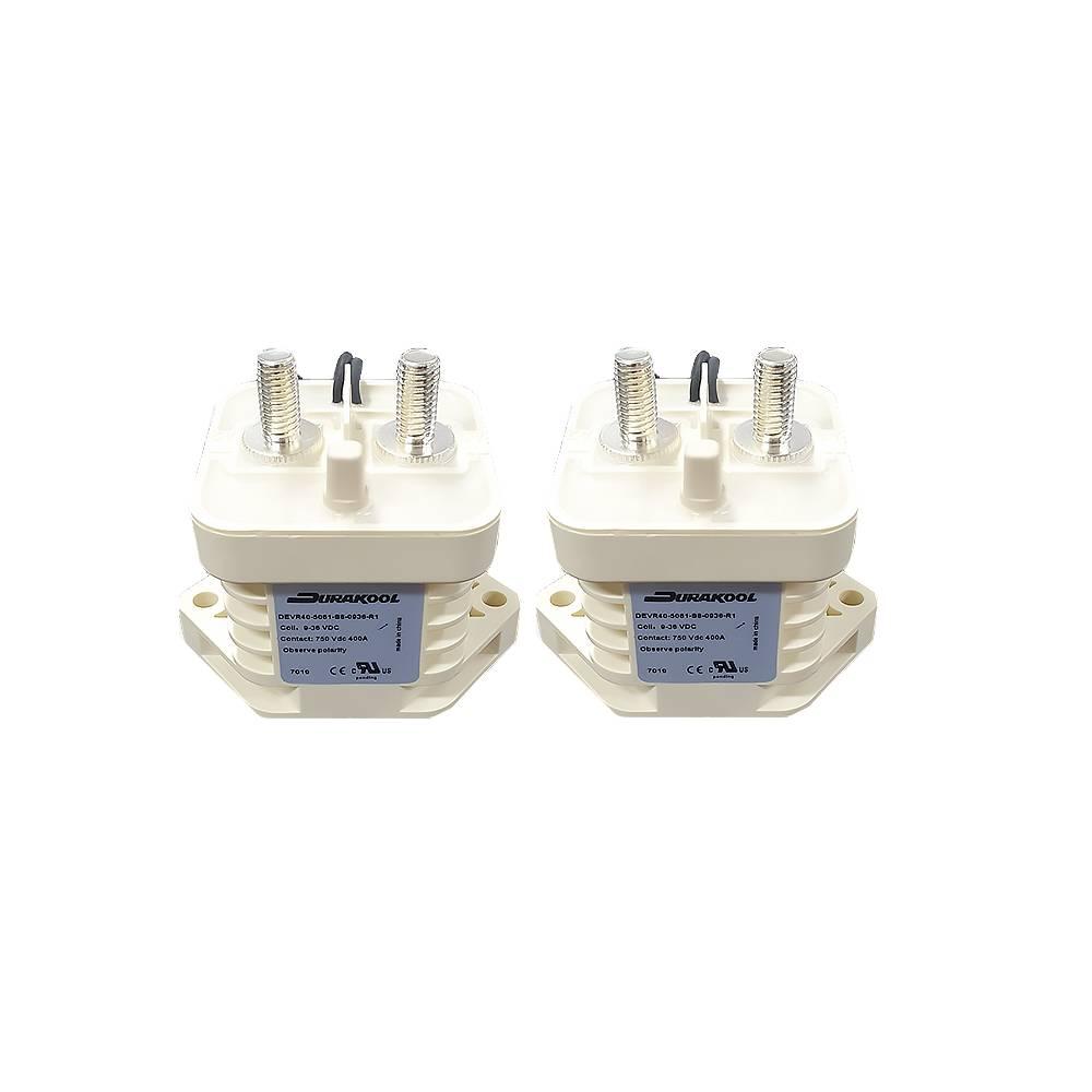
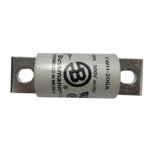
Everything in the box. The CCS bus HV connectors are not supplied (choose a passthrough or connector to suit) - use ≥ 70 mm² cable rated for 200 A continuous, no splicing.
Installation
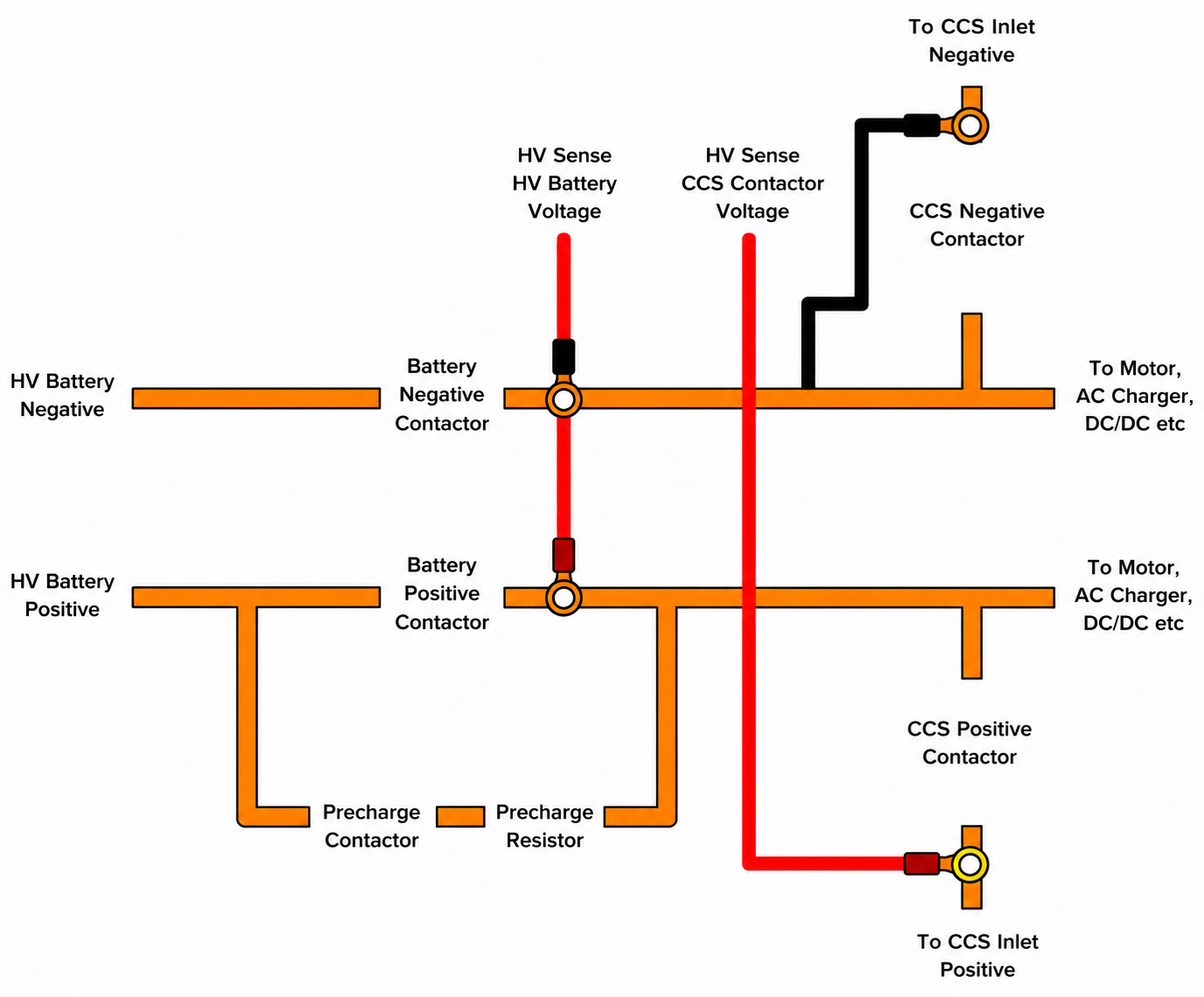
Work through the mounting sequence. Design the HV architecture around a second, CCS-dedicated HV bus that's only live during fast charging - no un-switched live HV should leave the battery box.
High-voltage wiring
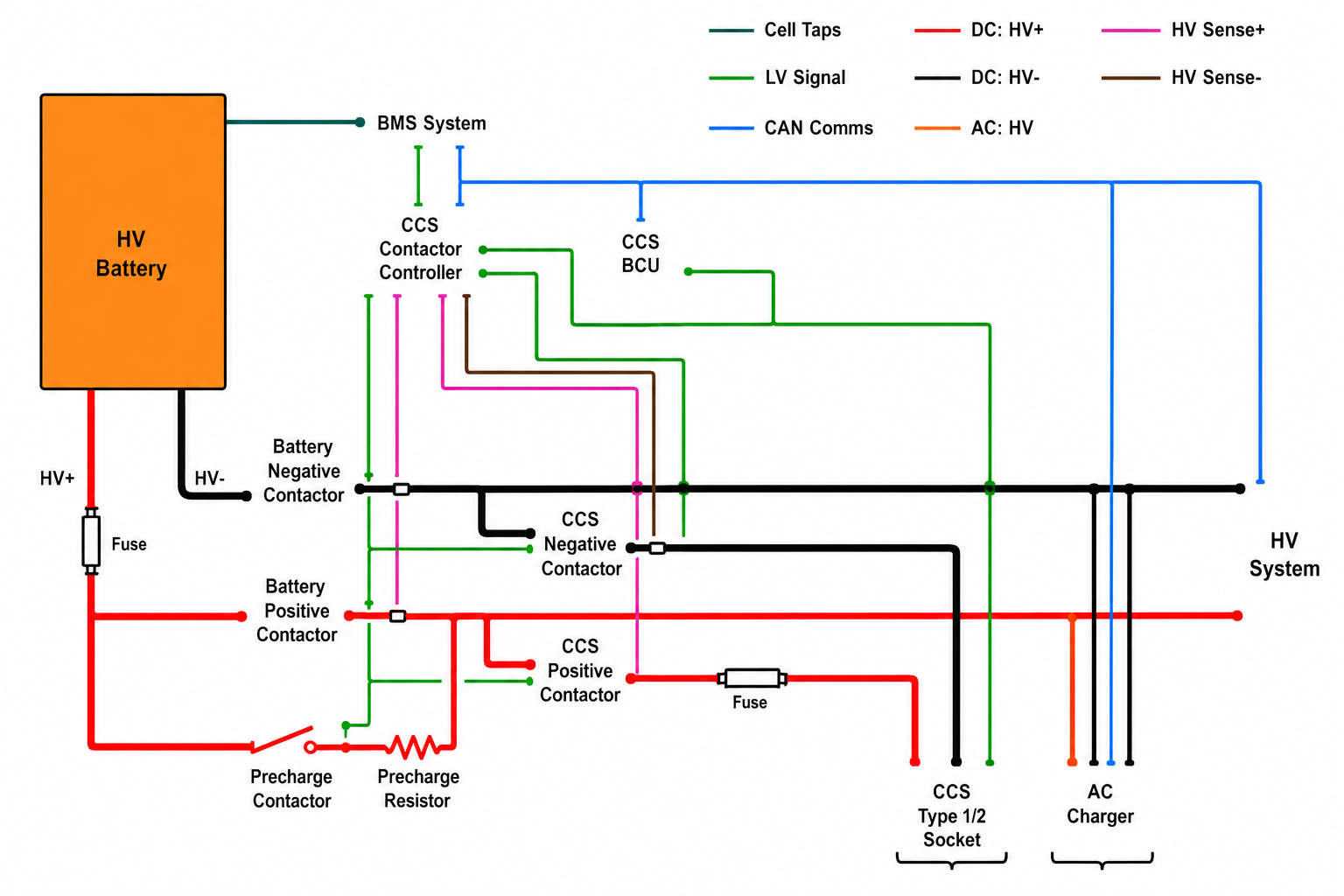
The contactor controller drives five contactors and taps HV sense after the battery and CCS contactors.
Connectors & pin-outs
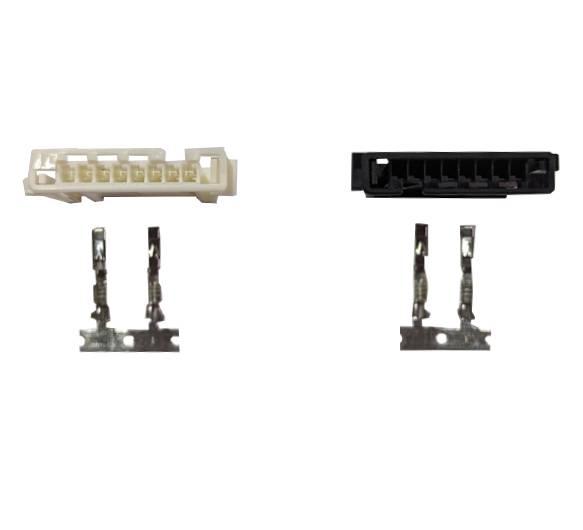
Every harness connector and its pins. HV sense: HV0 = battery (beige), HV1 = CCS inlet (black), taken after the respective contactors - polarity-critical. Search to filter.
Status & fault codes
The stop-switch LED shows charge status and, on a fault, blinks RED a number of times followed by one long BLUE.
state: white
Fault codes (RED blinks)
Status colours — AC / standby
Status colours — DC fast charge
Software setup
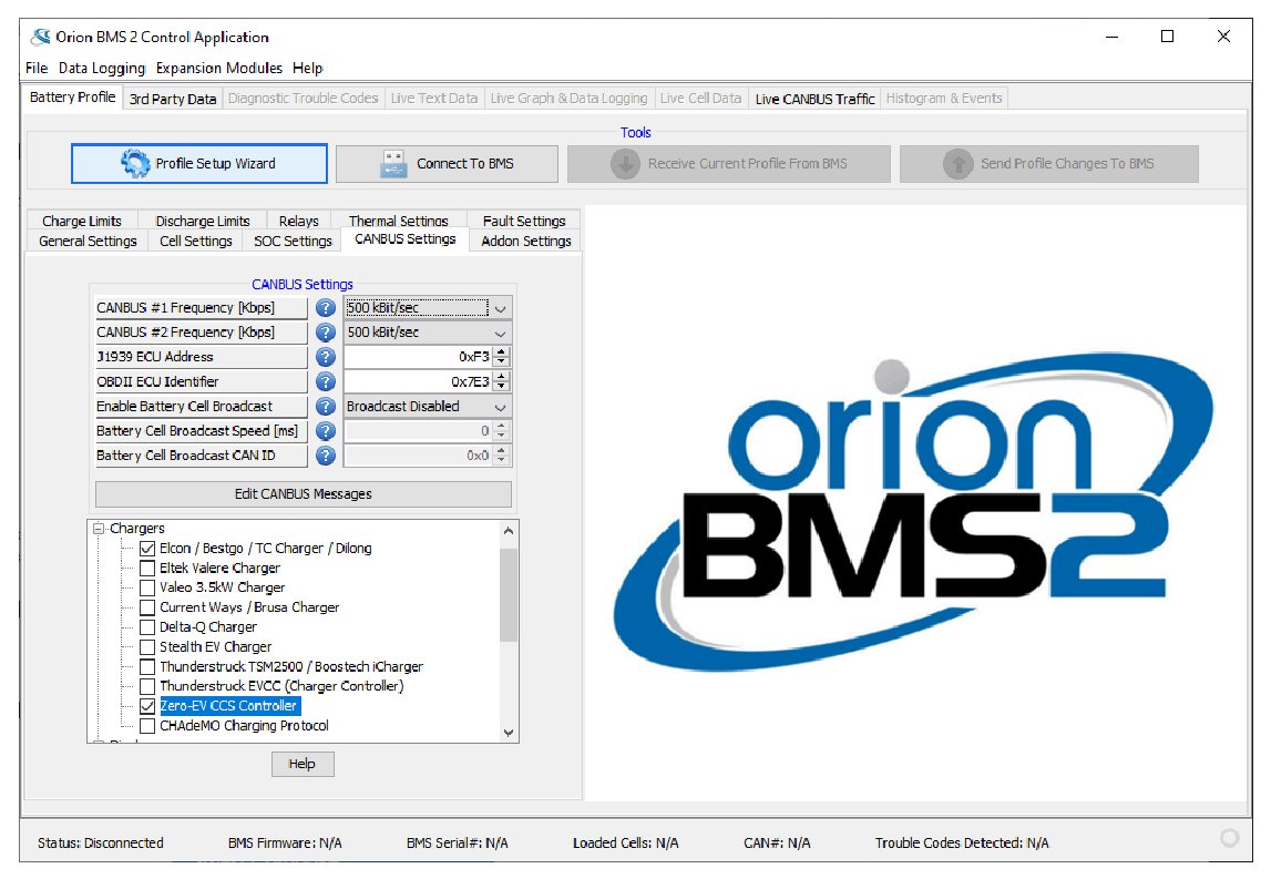
Configured through the Orion BMS Utility. Keep the HVIL open until this is done, to stop the contactors closing during setup.
Troubleshooting
Common symptoms and where to look. Some AC/DC chargers use protocols not yet widely adopted - if one doesn't work, contact Fellten (currently Shell chargers are known-incompatible).
Documents & downloads
The full user guide, harness drawings and related guides. Links open in a new tab.